
i know that the way i am asking to do this operation is wrong. but i dont know the right way?
if it helps, im using AUTODESK Autocad 2010.
help please,
thankyou,
KNM


 RKM 3D Designs

i know that the way i am asking to do this operation is wrong. but i dont know the right way?
if it helps, im using AUTODESK Autocad 2010.
help please,
thankyou,
KNM
 The Beast from the East

You should be able to move the cylinder into the block with a normal move command. After that, select both objects and click on the Subtract button (or use the subtract command keyboard input) and I think it may ask you which piece you want to keep, so you'll select the rectangular block and hit enter.
The Subtract button is located on your solid editing ribbon and it's one of the three buttons that looks like a venn diagram.
RKM 3D Designs
WORKED,Originally Posted by splat15k
but i cant tell, that it is a chunk taken out in the 3-D view,
do i need to add a light source?
thankyou,
KNM
The Beast from the East
Load the "Visual Styles" toolbar and it will give you a couple of viewing/rendering options.
You can also use the RENDER keyboard command, but I find that takes too long.
RKM 3D Designs
i have it on the style that is rendered as conceptual, and normal.
this is how it is showing.
lmk what you think is the problem
thankyou,
KNM
The Beast from the East
That doesn't look quite right, but I'm not sure what would be causing those strangely angled lines. Perhaps those edge effects need to be turned off.
RKM 3D Designs
how woulld i turn them off?
hey hey hey,
re-drew the drawing,and now no lines looks exactly how i wanted.
thankyou again, for all the help
,
more questions most likely to come.
thankyou,
Ryan M.
Last edited by knownothingmags; 08-09-2012 at 05:49 PM.
Learning Mag-Fu

Looks like you cut the surface but didnt remove... ill fire up my work laptop in a bit and see if i can get you a better answer. The strange lines on the surface are there because its connecting the nodes from the 'cylinder' to create the surface.
The Beast from the East
Good call, that's probably what happened!
RKM 3D Designs
so i got the line problems fixed and the lighting,
now:
when i go to subtract an object from another how do i get things perfectly center?
RKM 3D Designs
is there just a centering tool, to apply to obejects?
Learning Mag-Fu
no, no centering tool... not really anyhow. The best thing to do is draw "construction lines" to locate the center of your circle... draw your circle... then delete your construction lines.
I also looked into your subtract question... what might be easier for you is to use the "press/pull" tool. Draw your circle on the face you want to cut it out of, then "press" it through the depth of your shape.
LMK if you have more questions... i work for an autodesk reseller and answer tech support stuff all day... i may as well continue into the evening
RKM 3D Designs
awsome. thankyou for the tip with the construction line.
Question,
do i need to put sizes and scaling in my drawing, or is that all applied by the cnc or mill operator?
im lost when it comes to the production side of my drawing.
anyone who can get me some light on this would be helpful.
and of course more questions to come,
KNM
Learning Mag-Fu
Generally speaking you draw everything on cad applications at true scale. If its large or very small you might scale it to print it.
RKM 3D Designs
so however i draw it is fine?
or
if i want a peice to be 10mm x 10mm x 2mm i would draw it on cad 10 x 10 x 2?
,
KNM
Learning Mag-Fu
Ohh I gotcha... There is a units setting for each drawing file. Type units at the command line and you can set it.
RKM 3D Designs
awsome.
thanktou,
KNM
RKM 3D Designs
hey squid,
what file extension would somone have to save their work in solid works for me to be able to open it up in autodesk autocad 3D as a solid image/ 3D image.
thankyou,
Ryan M.
Learning Mag-Fu
Solid works should be able to export to DWG which should work for you!
RKM 3D Designs
ok i let my guy know. he is on different time so ill see what he comes up with.
RKM 3D Designs
so aparently i am thinking way to small when it comes to 3d drawing.
i just watch a guy make a pitcher for pooring water out of just a few lines.
full 3D in the end.
i have so much to learn.

RKM 3D Designs
how do i make these 3 seprate objects exactly the way they are but filling the voids and making this on solid object?
help please.
thankyou,
KNM.
 Registered User
i would create a polyline using the three endpoints of your triangular area then extrude it the length of your rails, then repeat on the other side. once you have your gaps filled use union to join everything together.
RKM 3D Designs
yeah buddy,
thankyou,
KNM.
RKM 3D Designs
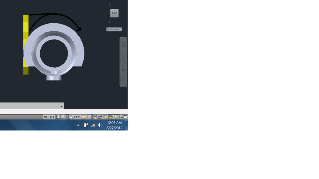
how do i get the top of the yellow to wrap around the other object?
and
to protrude into the body the same way the bottom half of the yellow object is.
any of this make sense?
is this even possible?
Learning Mag-Fu
How did you create the yellow object?
RKM 3D Designs
its the AO honey comb logo, built from boxes.
then after i made a hexigon i copied it and snaped six copies to the center origional and then, used union to make all 7 peices one.
that help?
 Posting Permissions


 Reply With Quote

