


Here is an update on where I'm at with this:
I have a total of 3 pods of paint through the configuration in the first post.
Pod # 1 Using Draxus Bronze Blaze: Fed perfectly fine, no chops but I did have one barrel break because the paint was crappy (I tried the paint in 4 different markers and had barrel breaks with all of them)
Pod # 2 Using All Star paint: Fed perfect, no breaks, no chops Approx 90 degrees outside when I did this one.
Pod # 3 Using All Star Paint: I shot this one immediately after #2. I had left the pod sitting in direct sun for 45 minutes before I shot it. The outside of the pod measured 105.4 deg. at the point I used it. This one fed perfectly fine, no breaks but I did have one I would call a "leaker" meaning that it did not full on break, but was leaking just a little fill down the barrel and one small spot in an elbow.
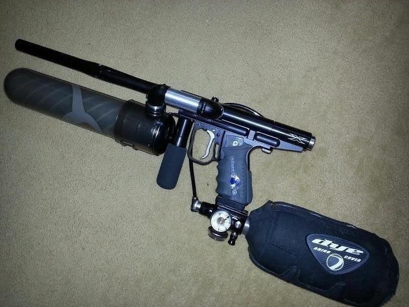
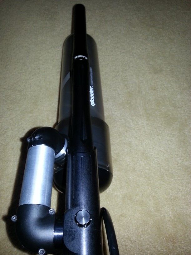
On to my current configuration:
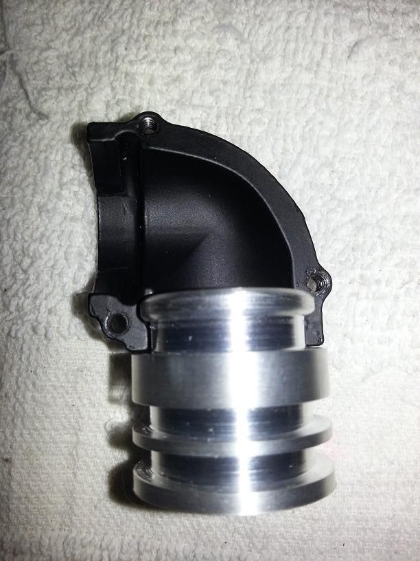
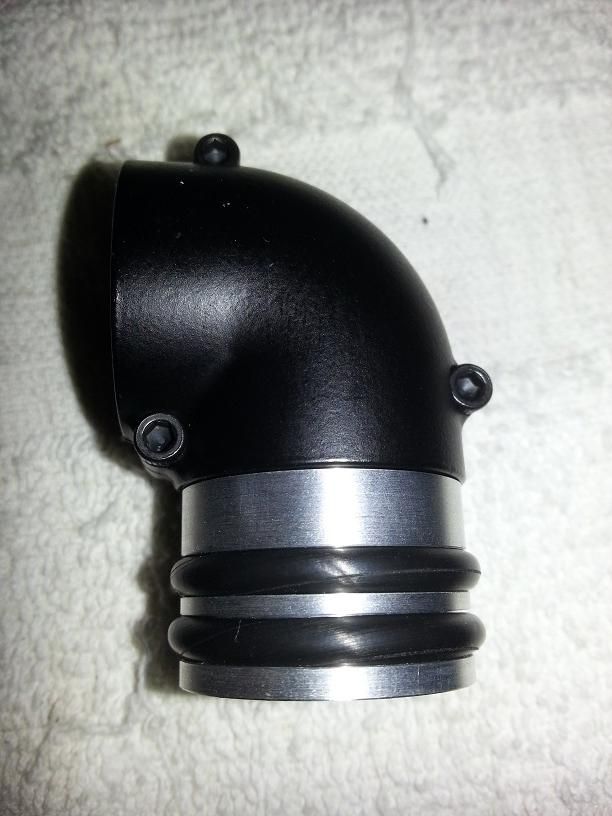
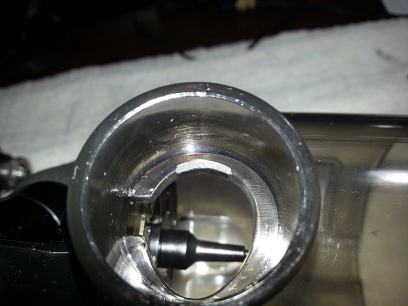
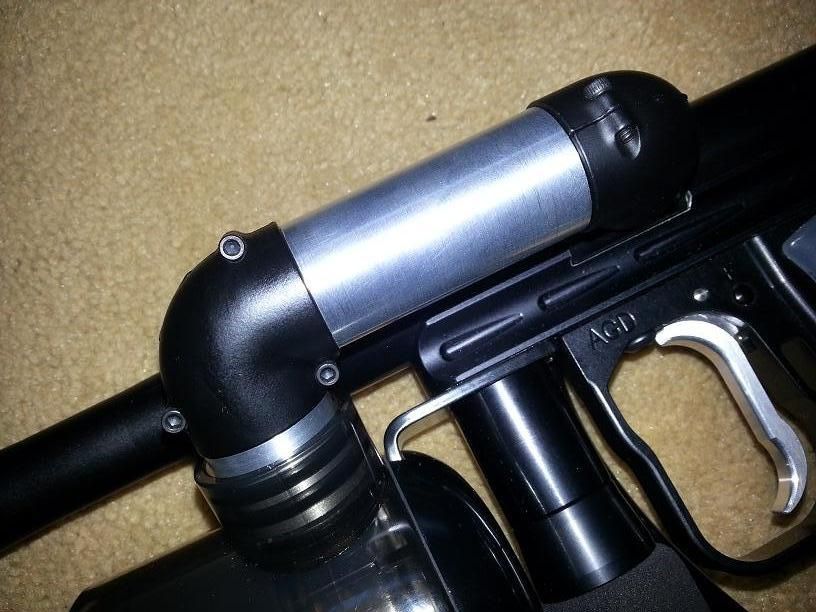
I redesigned my socket to elbow adapter to have two o-rings. It stayed in place just fine with the single o-ring, the two o-rings make it more rigid side to side though, so it won't be as likely to move if I knock it against a bunker or tree.
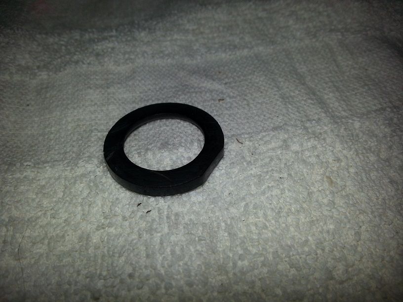
I modified the feed guide to hold the ball gate in place under my adapter. I just cut off the "tube" part of it leaving what amounts to a black plastic washer.
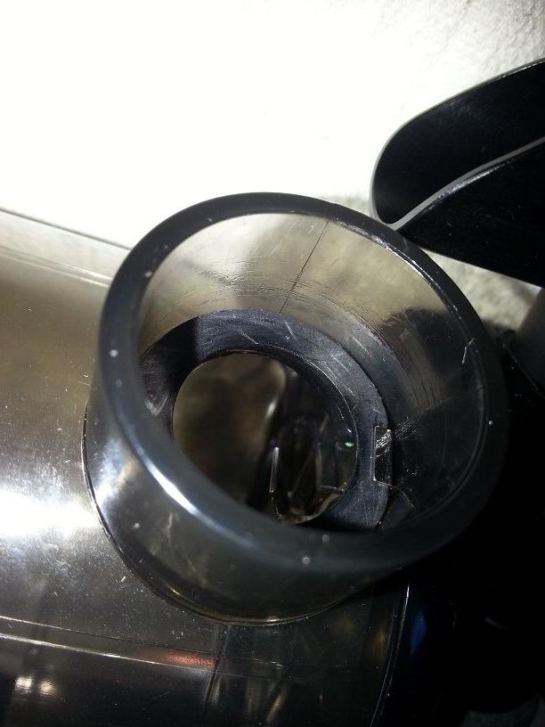
I found that there was a nub molded into the Q socket that was preventing the feed guide from sitting squarely in the feedneck. I sanded this nub down until the feed guide and my adapter fit without a gap.
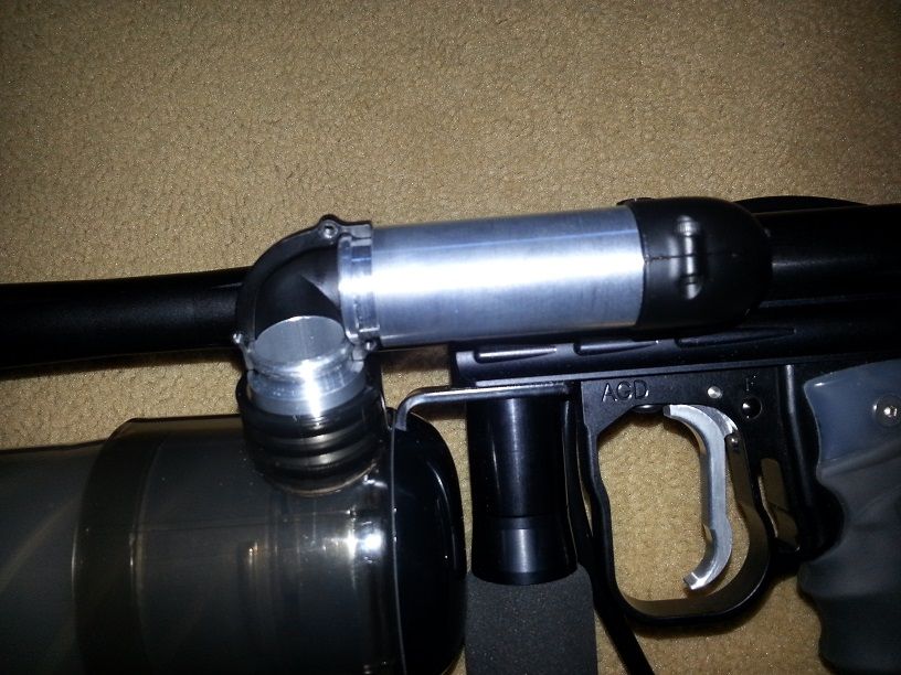
I also made up the horizontal feed tube piece out of aluminum.
I've put one pod of All Star through this setup so far. The entire pod fed without any problems whatsoever.
The one thing i don't like about the aluminum horizontal feed tube is that it makes it more difficult to take apart for cleaning. I have a couple ideas on how to modify the ends of the feed tube to alleviate this problem. I will be trying these out soon.


 Reply With Quote


