
Any chance you could mock the grips up on a AM/MM length rail.


 Formerly lancecst
Any chance you could mock the grips up on a AM/MM length rail.
lukescustoms.com
 lukescustoms.com

Ok, here you go, actually it's doesn't look to bad, and much nicer in person.

 RKM 3D Designs

will there be a place on the right side and the bottom for air inputs?
so we can have a gas thru effect for the valve?
Formerly lancecst
I really like the look of that on the am/mm rail. I'm in when you get to the plain foregrip version.
lukescustoms.com
Yes of course, that's been pretty much covered (One page back shows pictures of the port)...Originally Posted by knownothingmags

This is a gas-through foregrip with bonus LPR.
Run air supply to your valve off this port.
This is the bottom of the LPR-FG, air supply in and low pressure adjustment.
This is recessed to hide your air fitting, plus it lets me remove some dead weight.

 OutKasT 4 Sho!!!

yeah man i was actually selling tha extra LPR testers that i built…an electro/pneumatic set up would be the way to go for testing tha CPS…if it can pass tha test of that then a MSV-2 will easily work with out any shoot down. test it in full auto at 27BPS for a couple of cases of paint and you should be all good.
its prolly best to to test the LPR at anywhere between 40-80psi….at 40psi tha LPR will be working its hardest to regulate and recharge and keep up with tha rate you cycling it at…at 80 its tha average PSI for most set-ups…maybe 70psi and that will give you a good gauge on how well you LPR works. something like this you will wanna take the proto type to hell and back before trying to market it.
OutKasT 4 Sho!!!
and slide check valves are very nice for testing tha LPRs…10/32 threaded slide checks that is
lukescustoms.com
Foregrips are probably a ways off, sorry.
This LPR is actually phase number 2 of 4 of a single project. Each phase is dependent on the previous being a success, meaning functionality and customer support. Phase number 3 and 4 have not really been discussed on the boards yet. If the LPR gets off the ground we can move forward with the rest.
Last edited by luke; 03-24-2014 at 09:20 AM.
lukescustoms.com
I'm not testing on a marker with paint. This will be a mechanical test using my knee mill to actuate the MSV-2. I can adjust my RPM to simulate trigger pulls per second.
I will actually chuck this up the vice on the milling machine to do my tests. I have a 'due-hickey' that will mount in the spindle and will actuate the MSV-2, think camshaft but with 2 lobes.
OutKasT 4 Sho!!!
kool kool
 ~pgop1.0
^^ Tits. I had a feeling the single trigger and shorter rail combo would look better.
 AO Zealot
K probably stupid comment... I want the a straight front design, without the grippy cuts, and just chop ALL that extra meat off... don't need to hide the fitting.
Warp Feed Evangelist
My Feedback
RKM 3D Designs
+1
 Registered User

That recession to hide the fitting looks pretty deep. Am I right in assuming that would make usage of CCM fittings harder and they would need an extension part to fit there?
lukescustoms.com
If you measure your fittings you will find that this is not excessively deep.
It is designed for maro/micro fittings and is wide enough to fit a 7/16" deep well socket. I believe some straight fittings can be installed with an allen wrench,
but I'm not familiar with everything on the market so the 7/16" socket should cover everything that is suitable for this application.
Are you guys familiar with the term "form follows function"?
If you study this CAD closely you will see that the shape is wrapped around the internal parts and air passages (form follows function)
Some of the internal cavities are not real clear but I assure "form follows function".
I would be willing to leave the rounded cuts out of the design if that is what you want. But it will increase weight that amount even if it is fractional, it all adds up though.
You guys are saying you don't want the bottom cavity, if I just drill and tap it at the bottom without the cavity it will increase the weight a tad more significantly.
If I 'remove' the bottom of the FG at the depth of the cavity i.e. making it 0.8715 shorter, it will look ridiculous (IMHO). The whole point of the project was building a LPR in a FG, so shorter is out for me.
The cavity is actually ULE milling allowing me to increase the LPR to FG length without adding all the extra weight.
At this time the only change I have planned is to remove a little more off the side edges of cavity on the bottom.
Pictures don't do these two designs justice and don't reflect how they feel in your hands. At some point you have to stop designing and move on with the project or kill it and move on to something else.
To be honest I have so much time (Not to mention $$) invested in this, I'm actually sick of it and am ready to move on to other things.
I'm just too deep to redesign, retool and reprogram these parts, the project is at a do or die point, sorry.
I'm extremely happy with both designs and have to stick to my guns, no hard feelings on my part either way.
Registered User
I like the overall look of the straight versionas it is now, but I can't figure how it will look on a marker all assembled (with lines and asa) ready to work.
Just to understand the design :
With the cavity as it's now, you'll have to use a straight macro fitting and the macroline will go out for the LPR in a curvy way to go to the asa. is it right ?
Perhaps, if you have time, you could install a macro fitting, macro line and asa to show us how it looks "ready to work"
Registered User
That's ok to me. I'm just thinking ahead what I'm going to need with this if I plan to use CCM 90degree fitting from the bottom of this to the asa under the grip.
lukescustoms.com
I don't think a 90* fitting will work, not sure if you can even install it, the design is meant for a straight fitting.
Registered User
Do do do.....
I personal like what I see, either the straight cut or curved design. My particular sight of interest is on utilize this lpr with a total luke mag. Trying to figure out how all the lines will flow. I do love when the grip is up next to the lpr so there is no gap. I'm not sure if the single trigger vert luke posted and the double trigger one has different lengths to correlate differently with the length of the rail.
Registered User
you can, you just need to use 1/8 female to male extender to get high enough from the bottom of that cavity.
lukescustoms.com
Yes, of course that would work.
lukescustoms.com
My parts just came in, here is a picture of a Microline fitting from Palmers, it does install with an allen wrench like the Macro fittings I've seen.
It sits less than 1/8" below the surface of the bottom of the grip.
The set screw on the left of the fitting is the LPR adjusting screw that was mentioned previously.
The cavity side wall size and shape will be addressed on the production run.

lukescustoms.com
My double and single trigger frames are identical in all ways except for the trigger guard shape, the length is identical.
-Put Up Or Shut Up-
Less weight, the better. Like you said Luke, everything starts to add up.
Registered User
This could be difficult because they don't screw with an allen wrench like the macros or micros.
Registered User
Thanks for the pic.
lukescustoms.com
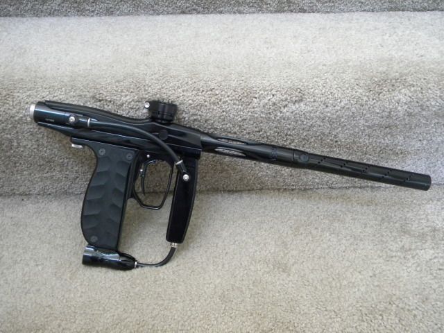
This is not really an original concept, there are tons of markers set up this way.
This is OPBNs marker with a recessed fitting (partially recessed anyway) on one of my foregrips.
Registered User
That's true.
In this particular setting (I've almost the same on my RPG mag), it's nice because the the frame is longer than the fg.
But I'm not sure it would look so nice with a short frame.
When I look at your pic of the lpr with your vert frame, I think it would be nicer with a 90 screwed at the bottom than it would look with a straight macro inside the lpr and the macro going out of it.
But it's just a personnal opinion about the "look", and I'm sure you do the maximum to get the best part possible.
Registered User
Won't be a problem. You can slot the top for a flat head screwdriver. Or thread lock to the macrofiting before insertion.
Registered User
Good idea !
I note it to remember it.
 Posting Permissions

 Reply With Quote


 [/URL]
