
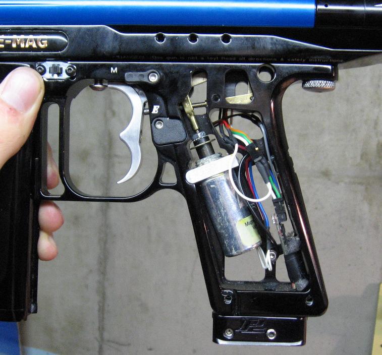
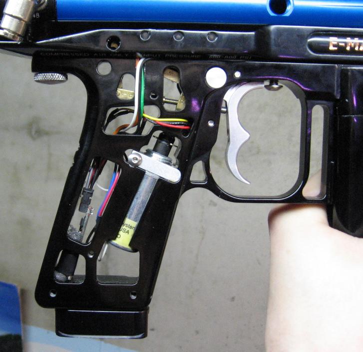
Isn't there a screw holding the ACE board to the frame? If so that is the ground. Then your left with the two wires that should be easy enough to figure were to place them.
Originally posted by BigEvil


Comment