
Originally posted by Nick E
thejere I think I know what your getting at mentioning the ULE trigger design, but I'm not sure if it will work quite the way your thinking. The ULE trigger relys on equal pressure on both sides of the "head".... where here, the larger "head" would have to be used to seal the power tube, and be exposed to large pressure differentials. If you used a small head(where it seals to the powertube) would create flow problems. let us know what you were thinking.
Anyone happen to know the size of the stock AGD dump chamber and what pressure it opperates at? If possible it would be nice to keep it the same so the Lvl x bolt and springs would still opperate about the same.....although flows through the on/off(powertube seal or whatever you want to call it) could have a large impact.
I had another idea about the placement of the ram, and seal but thats going to have to wait till tonite. I think it will allow for a smaller ram, and maybe the use of a 3 way instead of a 4way....
As for a retrofit to standard mag valves.....i wonder if anyones ever removed the sear and on/off(i mean o-rings to allow for straight through flow) and used a ram to actuate a lvlX bolt. It would have to be a decent strenght ram, because with the constant flow through the on/off the bolt would still have force pushing it forward after the ball is fired. But, if the combination ram/spring pushed the bolt back onto the powertube, it could easily hold it back because of the lvlX low initial force. If set up properly the lvlX should still even be effective.....plus it would look cool having a ram on the side of a mag lol (really the ram could be built into the rail since there is no need for a sear or on/off anymore.....dunnoo if it could work around the grip scrwe tho)
someone stop me, I have work to do lol

 [/IMG]
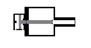


Comment