AO: We are back from the dead... again! After an 18 day outage, we are finally alive and well. Who knew how complicated updating software/databases from 2008 would be. I still have alot of tweaks to make, but my main goal was getting everything patched and updated to 2026.
Vbulletin 6 has changed alot since 2008 so we will have a ton of new features to dig into.
Awesome! This project is still the most interesting to me because I love warpfed markers but hate the weight of a warpfeed. My warpless Z3 is working for me, but the Rotor is still my favorite loader by far.
working on the damn shape for the top shell to seat to the bottom shell.
i need my other printer up in this second office so i dont have to keep running down to the basement office where everything else is :rofl:
It really shouldn't be too much of a problem to take out the internals and then go through the bottom of the loader with a 1" drill bit into the top shell. That gets you perfect placement of the hole for when you drop in the box rotor parts (and it may even be able to be completely covered up by an unmodified/undrilled "color kit"). I'm just still deciding on what to use as the vertical pipe, and how to fix it in place to the upper shell to keep it from moving and messing up the alignment with the vertical feed spout from the box rotor parts. I'm thinking maybe a piece of super-warp-hose with a coating of epoxy, maybe...
By the way, I bought a hi-cap shell specifically for this mod. I'm not too worried about messing up the top shell. When I modded the Prophecy Z2 there was much more at risk in terms of cutting and drilling parts, lol
I need this. @knownothingmags, quit your day job and just do this. Also should it be expected that there would be a decrease in feed speed? My mag is a hungry beast when i rapid fire it. Could you potentially fit the box rotor motor in there or is there not enough room? You know what actually just redisign a whole shell whe re you can fit a box rotor motor in there plus be warpless feed and sell the design to dye, of course after we get our beta test prototype models that is.
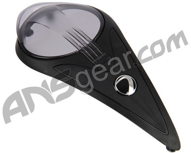
KNM - not to beat a dead horse. I've followed your response and progress on your other thread with having to redesign a whole hopper build around the guts of rotor/box mag. As I look back at wingbatwu's original posting of his modification. What are your thoughts around making the adapting piece printed from the "top carrier" trim piece that mounts to the rotor top and attaches to the lid of the rotor. I've linked the piece from ANS showing the top carrier as a accessory that comes in different colors for people to interchange. It appears that his modified brass elbow penetrates the hopper top through the area where the lid carrier is attached to the top of the rotor by 5 screws. Without truly knowing the difficulty or ease of my question, I wonder if a printed lid carrier maybe a practical answer? This new printed lid carrier would still utilize the mounting screws attachment points of the top of the rotor. The part that would need to be printed would contain a printed conduit/tube that hovers over the internal parts of the rotary assembly from the box mag and carries a specified trajectory out the top placing the exit behind the lid hinge. Since this rotary assembly rotates/spins some relative accuracy would need to be accomplished where it sits above the assembly but provides a close connection where the path of the balls can enter and be channeled out the top of the lid carrier. The portion of printed conduit/tube could terminate outside of the top of the cover behind the lid (near where the dye emblem is placed in the linked color kit from ANS) with some type of flange to match the ID of common qloader/warp feed tubing. This approach would require a hole to be placed directly behind the hinge of the rotor lid of the top shell, which would be fairly simple to drill/dremel for the end user. It would be quit simple to install since its utilizing the same mounting screws for the lid top and the hinge of the lid attachment joint. Thinking out loud, it appears to be a feasible solution built off of wingbatwu's design without having to create from scratch? Ideally, this would allow a simple mount of the printed part through the same manor that his design produced results, just looking a little cleaner with printed parts. I hope you can understand what I described above, and again just a thought.
ANSgear is the worlds largest online paintball store. Huge selection of Paintball Guns, Tanks, Masks, Loaders, Harnesses, Barrels and more. Fast & Free shipping will keep you up to date with all of the best paintball gear.
KNM - not to beat a dead horse. I've followed your response and progress on your other thread with having to redesign a whole hopper build around the guts of rotor/box mag. As I look back at wingbatwu's original posting of his modification. What are your thoughts around making the adapting piece printed from the "top carrier" trim piece that mounts to the rotor top and attaches to the lid of the rotor. I've linked the piece from ANS showing the top carrier as a accessory that comes in different colors for people to interchange. It appears that his modified brass elbow penetrates the hopper top through the area where the lid carrier is attached to the top of the rotor by 5 screws. Without truly knowing the difficulty or ease of my question, I wonder if a printed lid carrier maybe a practical answer? This new printed lid carrier would still utilize the mounting screws attachment points of the top of the rotor. The part that would need to be printed would contain a printed conduit/tube that hovers over the internal parts of the rotary assembly from the box mag and carries a specified trajectory out the top placing the exit behind the lid hinge. Since this rotary assembly rotates/spins some relative accuracy would need to be accomplished where it sits above the assembly but provides a close connection where the path of the balls can enter and be channeled out the top of the lid carrier. The portion of printed conduit/tube could terminate outside of the top of the cover behind the lid (near where the dye emblem is placed in the linked color kit from ANS) with some type of flange to match the ID of common qloader/warp feed tubing. This approach would require a hole to be placed directly behind the hinge of the rotor lid of the top shell, which would be fairly simple to drill/dremel for the end user. It would be quit simple to install since its utilizing the same mounting screws for the lid top and the hinge of the lid attachment joint. Thinking out loud, it appears to be a feasible solution built off of wingbatwu's design without having to create from scratch? Ideally, this would allow a simple mount of the printed part through the same manor that his design produced results, just looking a little cleaner with printed parts. I hope you can understand what I described above, and again just a thought.
this is great input ill look into what I have here and throw something together. I know exactly what you are saying to do.
I have a few thoughts, I my run into some troubles. but nothing that taking the time to look at it wont hurt.
this is a great way of looking at things.
at this moment in time im not able to absorb all of your text right now (at work) so ill take a look at it again later tonight when I get home.
***edit, I get exactly what are saying. ill throw something in my thread later, I totally didn't see I was in his thread. I don't want to distract from what has been accomplished here.


Comment